Internal Stresses
Free Body Diagrams with a Cut
To create a free body diagram of internal stresses, place a cut somewhere in the structure and draw the forces acting on either side of the cut.
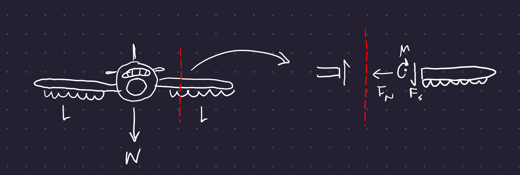
0.1 Convention for Internal Forces
0.1.1 Axial Force

Symbol: N
Tension is positive
0.1.2 Shear Force
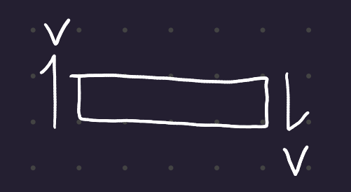
Symbol: V
Clockwise is positive. Shear comes in a couple.
0.1.3 Bending moment
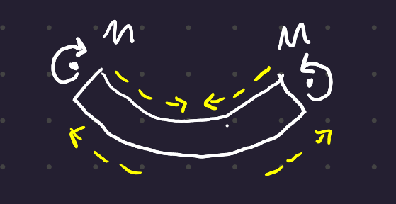
Symbol: M
Sagging is positive. In sagging, there is compression at the top of the beam and tension at the bottom, and in hogging those forces are reversed.
Remember, sagging is happy (positive) and hogging is sad (negative)
1 Diagramming Shear and Moment
A plot of the shear forces along a beam is a shear force diagram; a plot of the bending moments with respect to x is called a bending moment diagram.
1.1 Example 1:
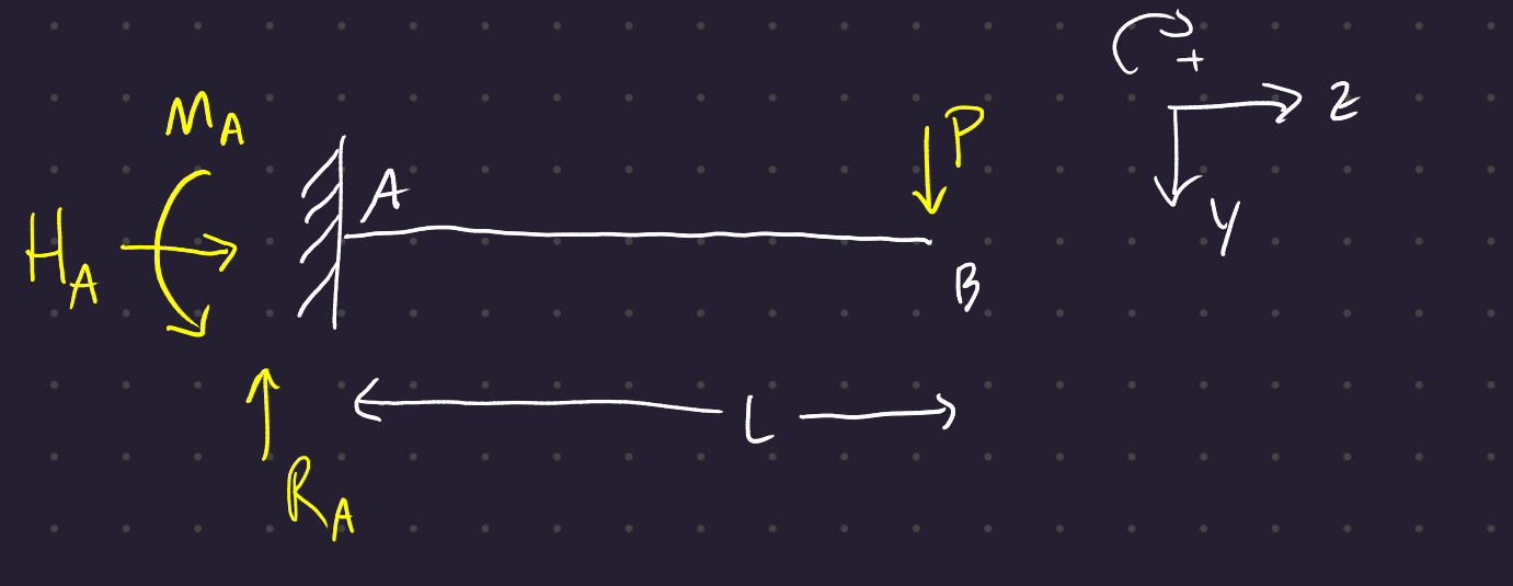
We set up our five equilibrium equations:
\begin{align} \Sigma F_H = 0 &\Rightarrow H_A = 0 \\ \Sigma F_V = 0 &\Rightarrow R_A = P \\ \Sigma M = 0 &\Rightarrow M_A = P\,L \end{align}
To find the internal stresses, we cut the beam at anny coordinate z an d determine the internal stress resultants N(z), V(z), and M(z) at that point.
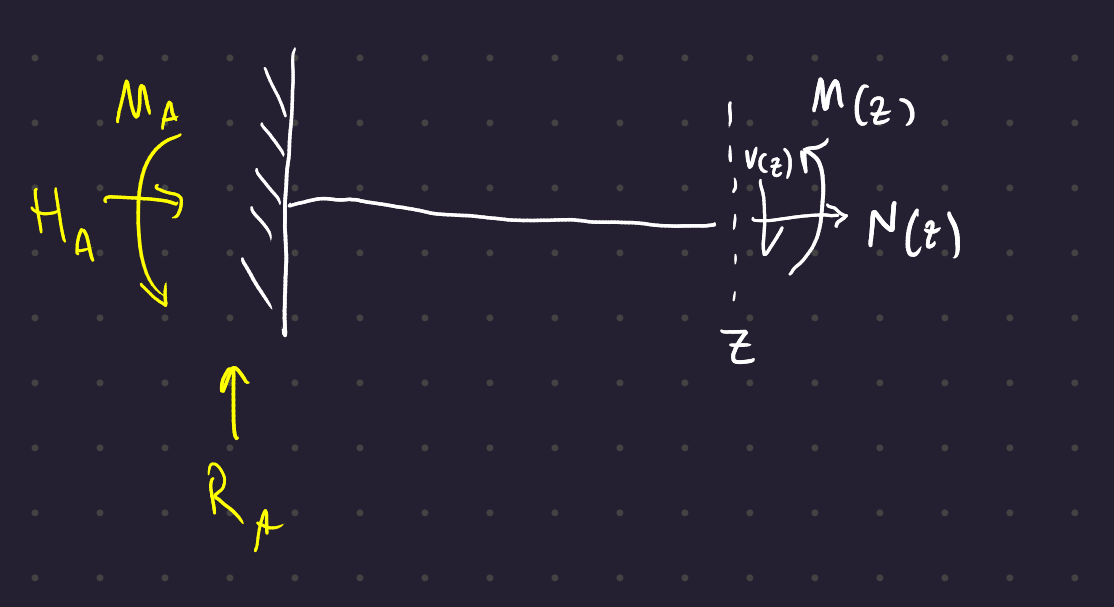
We set up the same equations again (taking the sum of moments at the point of the cut):
\begin{align} \Sigma F_H = 0 \hspace{2em} &\Rightarrow H_A = N(z) \hspace{2em} \Rightarrow N(z) = 0 \\ \Sigma F_V = 0 \hspace{2em} &\Rightarrow R_A = V(z) \\ \Sigma M_z = 0 \hspace{2em} &\Rightarrow M(z) = M_A - R_A \, z \end{align}
That last moment equation further simplifies:
\begin{gather} M(z) + M_A - R_A\,z = 0 \\ M(z) + P\,L - P\,z = 0 \\ \therefore M(z) = P(z-l)
1.1.1 Shear Force Diagram
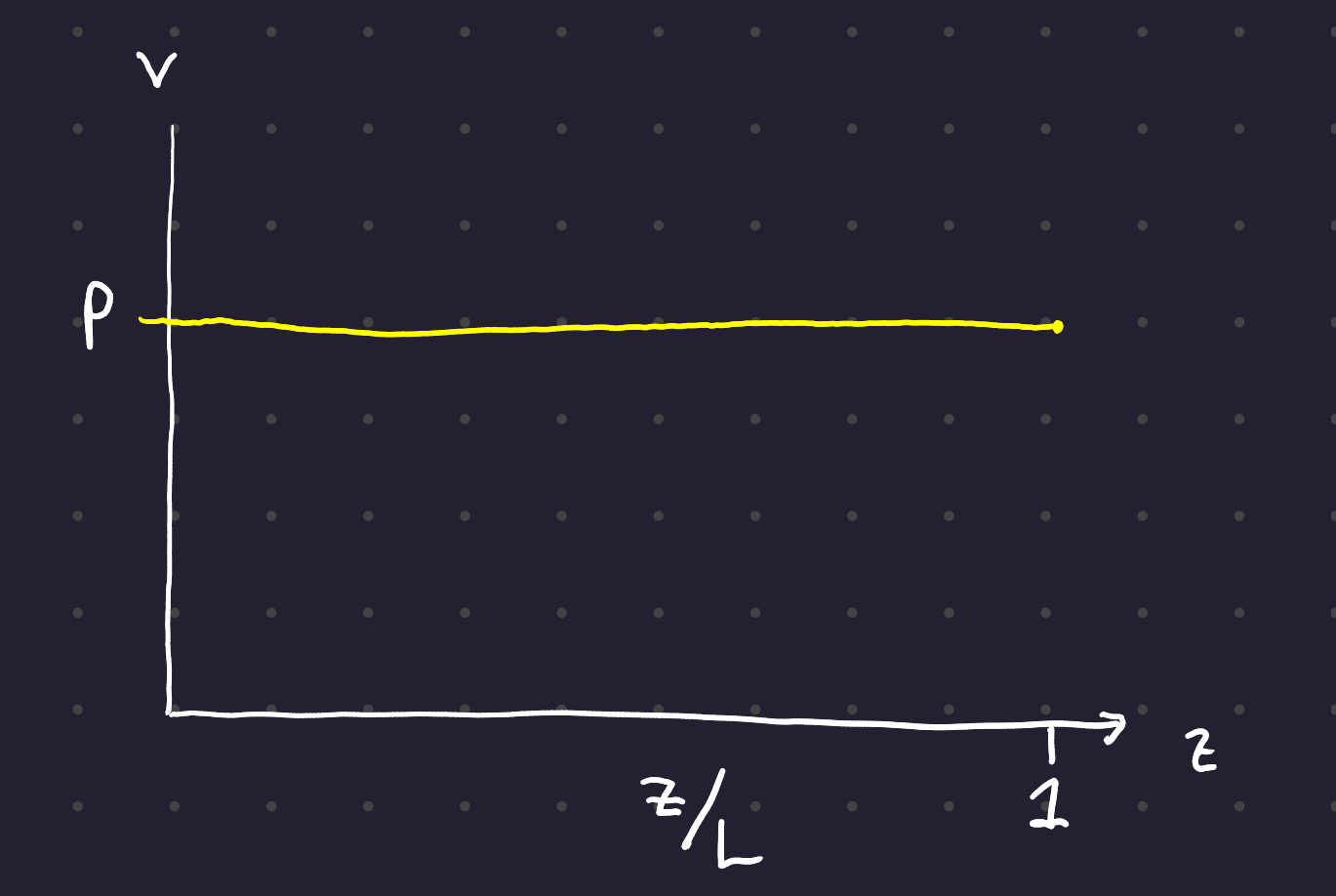
Since V is unchanging with z, this graph is a straight line.
1.1.2 Bending Moment Diagram
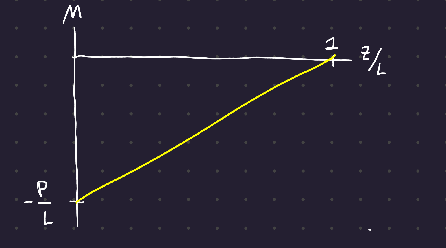
We go from -P/L at z = 0 to 0 at z = l. The moment starts negative and goes to zero; this means that the beam is hogging less and less over its length.
1.2 Bending Moment in a Beam
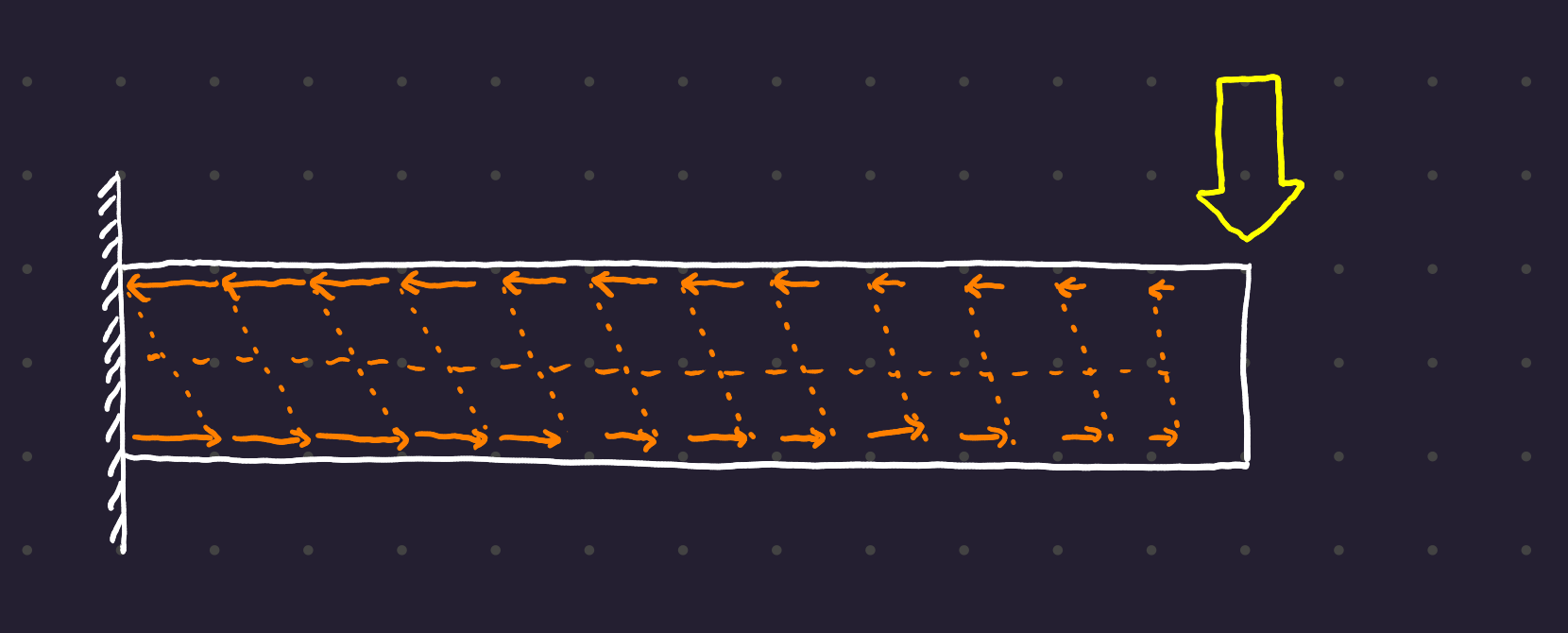
Note that the shear force at a point is the derivative of the bending moment at the same point.
2 Shear Force under a uniformly distributed load:
Here is our setup:
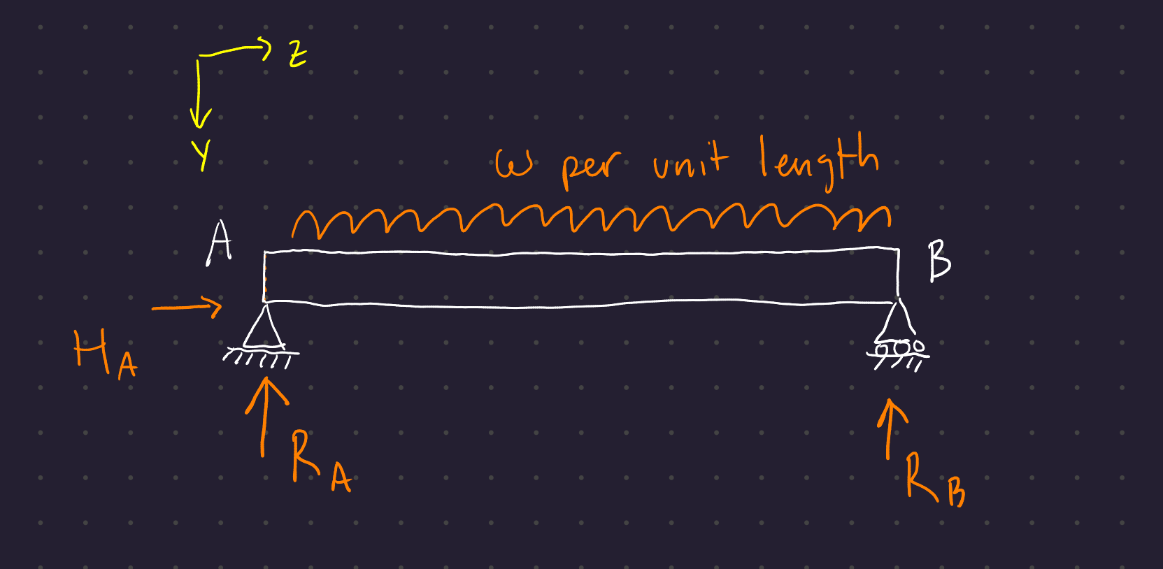
Let l be the length of the rod.
An equally distributed force creates a moment acting about the point halfway across the distributed load.
We set up our global equilibrium equations:
\begin{align} \Sigma F_H = 0 \hspace{2em} &\Rightarrow H_A = 0 \\ \Sigma F_V = 0 \hspace{2em} &\Rightarrow R_A + R_B = \omega \, l \\ \Sigma M_z = 0 \hspace{2em} &\Rightarrow R_B \, l - \omega \, \frac{l}{2} = 0 \end{align}
So R_B is equal to R_A is equal to \omega \, l /2.
Now cut the beam at an arbitrary point z:
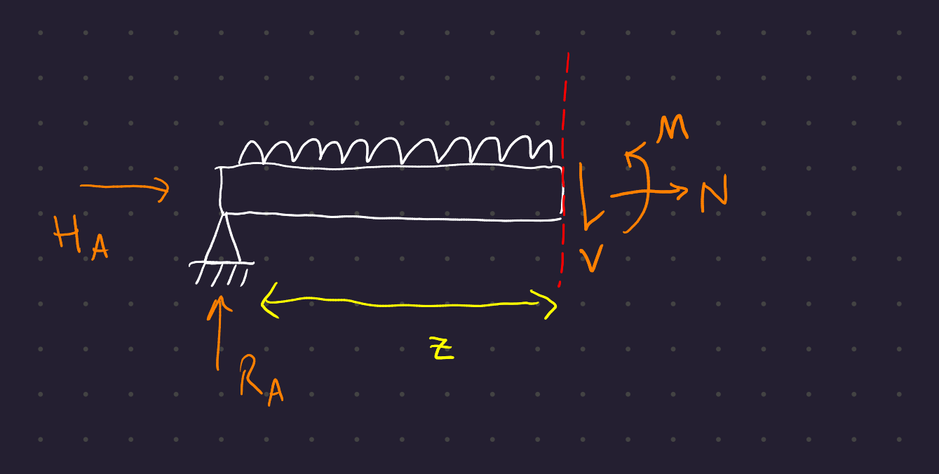
The moment and shear forces can be found simply through the same equilibrium equations:
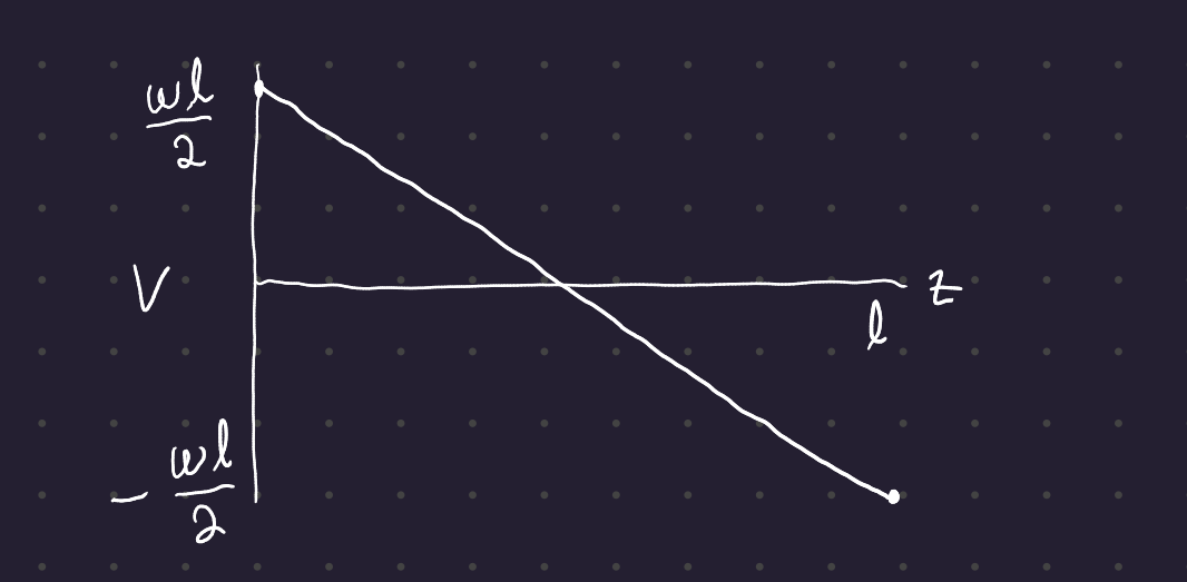
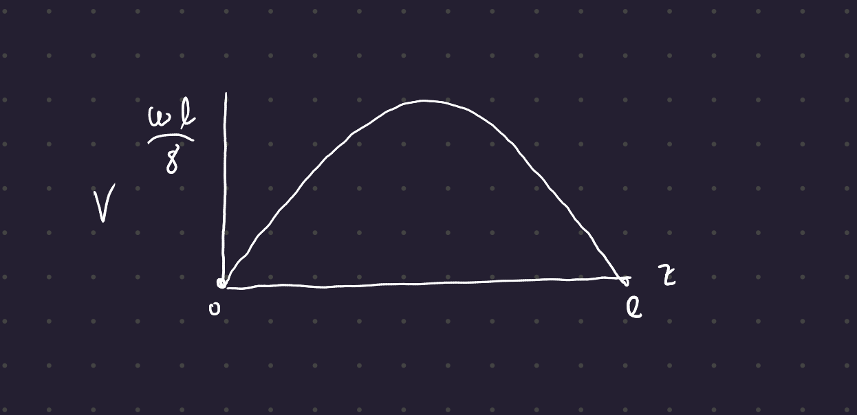
\begin{gather} V + \omega z - R_A = 0 \\ \Rightarrow V = \frac{\omega l}{2} - \omega z = \omega \left( \frac{l}{2} - z \right) \\ M(z) = R_A z - \omega z \frac{z}{2} = \frac{\omega}{2} (l - z)z \end{gather}
So our shear diagram has a negative slope from \omega l / 2 to -\omega l / 2 across the length of the beam, and the bending moment diagram is a parabola from 0 to 0 with a peak (halfway across) of \omega l / 8.
3 M = \frac{d}{dl} V
Imagine a beam with some load function \omega(z). Take a differential element at some z:
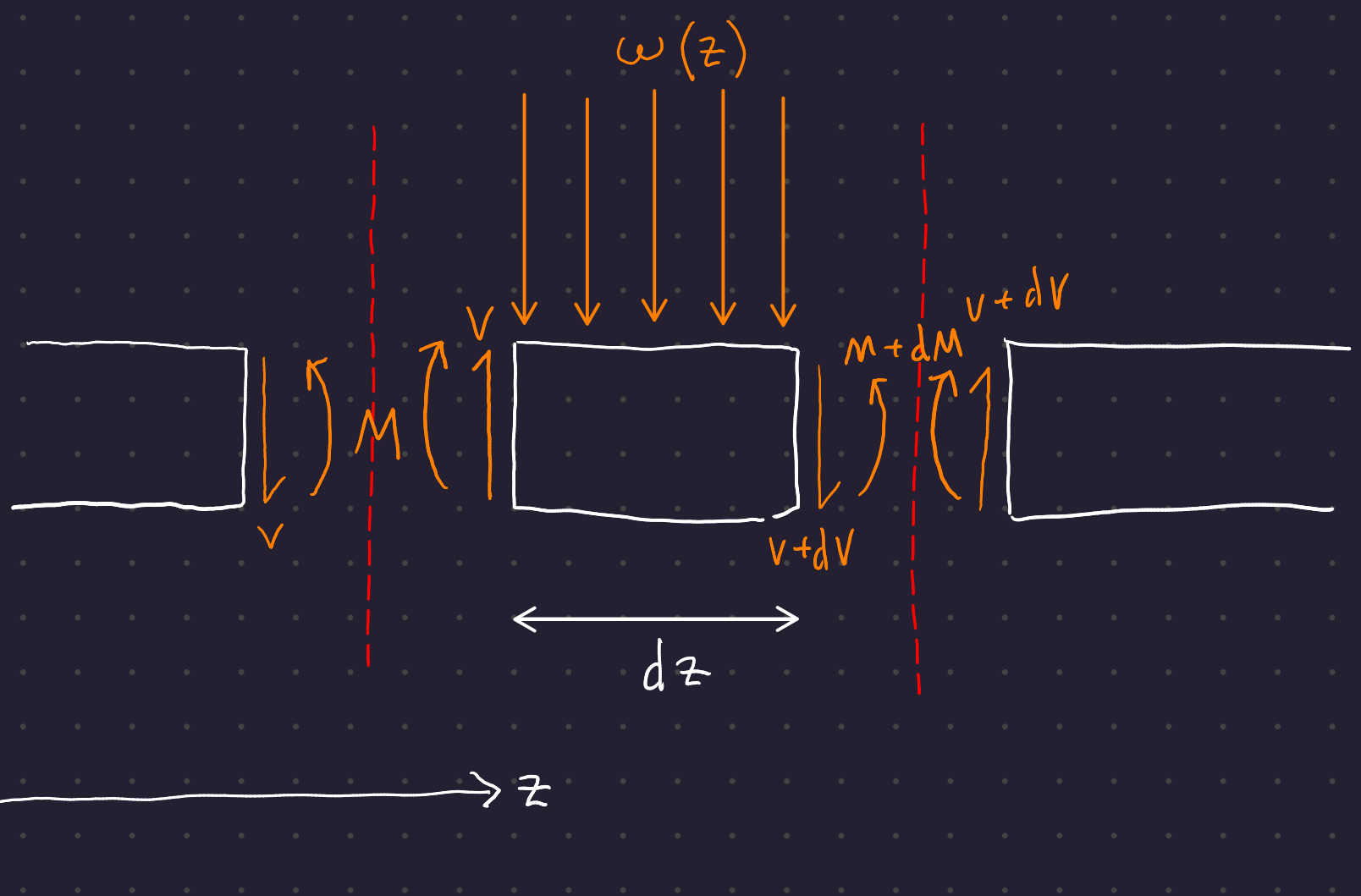
Set up some differential equations for the forces acting across the differential element (recall that \omega is a distributed load acting across the length dz of the differential element!)
\begin{gather} V - (V + dV) - \omega dz = 0 \\ \Rightarrow \frac{dV}{dz} = -\omega \end{gather}
Now examine the bending moment (take the bending moment around point z + dz):
\begin{gather} -M - Vdz + M + dM + \omega dz \frac{dz}{2} = 0 \\ V = \frac{dM}{dz} + \frac{\omega dz}{2} \end{gather}
Now take the limit as z\to 0:
\begin{gather} \lim_{z \to 0} \frac{dM}{dz} + \frac{\omega dz}{2} = \lim_{z \to 0} \frac{dM}{dz} + \lim_{z \to 0}\frac{\omega dz}{2} \\ \lim_{z \to 0} \frac{dM}{dz} = \frac{dM}{dz} \\ \lim_{z \to 0}\frac{\omega dz}{2} = 0 \\ \therefore \lim_{z \to 0} \frac{dM}{dz} + \frac{\omega dz}{2} = \frac{dM}{dz} \\ \end{gather}
Therefore the bending moment with respect to z is the derivative of the shear force with respect to z at a point.