Three Phase Systems
The entire power system is three phase until you get to the house level, at which point the power is tapped into single-phase supply.
10s of kW up to 10s of MW - three phase supply
Plugs:
Phases may be labelled L1, L2, and L3, or they may be labelled A phase, B phase, and C phase.
A single-phase plug has a maximum power output of 3 kW; a 3 phase plug has a max output of 86 kW.
1 How to generate 3-phase power:
To generate electricity, you take a magnet and place it inside a coil. The voltage E equals the rate of change of magnetic flux:
E = \frac{d\ \textnormal{flux}}{dt}
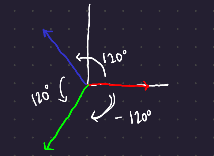
In contrast to a single phase generator, which has a single set of coils, a 3-phase generator has 3 sets of coils located at 120° intervals around the stator.
Generated voltages are generally referred to with the letter E, while voltages created from outside the system are generally referred to with the letter V.
When transmitting power over a distance, instead of giving each phase its own neutral connection, all of the phases share a neutral.
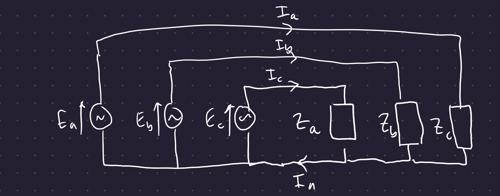
By Kirchoff’s current law, I_n = I_a + I_b + I_c. If the load on the system is perfectly balanced, ie all phases are 120° apart and the loads are balanced, then the current I_n is equal to 0.
1.1 Transmission lines
On high voltage transmission lines, you will see 6 wires - three on either side - and one thin wire on top.

The thin wire on top is a ground wire designed to mitigate the danger from lightning strikes hitting the power lines.
2 Three phase power
With balanced voltages and currents:
\begin{align} p_a &= V_{rms}\ I_{rms} \ \cos (\phi_V - \phi_I) - V_{rms} \ I_{rms} \ \cos(2\omega t + \phi_V + \phi_I)\\ p_b &= V_{rms}\ I_{rms} \ \cos (\phi_V - \phi_I) - V_{rms} \ I_{rms} \ \cos(2\omega t + \phi_V + \phi_I + 240°)\\ p_c &= V_{rms}\ I_{rms} \ \cos (\phi_V - \phi_I) - V_{rms} \ I_{rms} \ \cos(2\omega t + \phi_V + \phi_I - 240°) \\ \end{align}
The oscillating components cancel each other out. Unlike single-phase systems, where there are oscillating instantaneous powers, in a three-phase system, the electrical power is constant with respect to time. This makes generation much smoother, since there are never unbalanced torques acting on the stator.
If you have a balanced load, the overall power is 3 times the power in a single phase.
3 Star and Delta Connected Systems
Star and Delta are choices as to how you wire up individual loads. (The motor in the lab is delta-connected.)
3.1 Star connection:
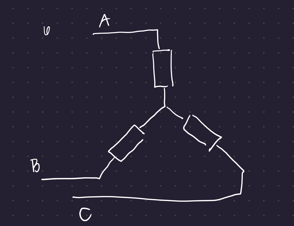
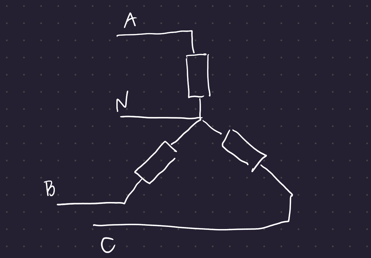
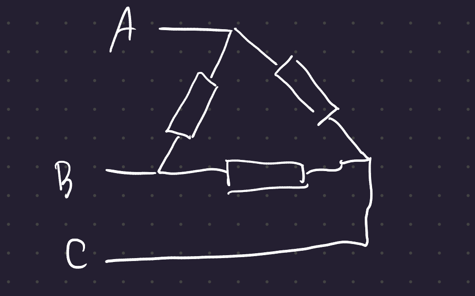
In the 3-wire and 4-wire star configurations, the neutral point in the center has 0 voltage at all times. So the voltage across each load is the phase voltage of each line.
Definition 1 (Phase Voltage) The voltage difference between a phase and the neutral point (assumed to be 0 for this level of course)
In a delta configuration, the voltage seen at each load is the line voltage.
Definition 2 (Line voltage) The voltage at one phase with respect to another phase
There are also two different currents you can measure for each phase. The current flowing through a load is the phase current I_{phase}. The current flowing through a line is the line current I_{line}.
In a star-connected system, by KCL, the line current is equal to the phase current. However, in a delta configuration, the line current and the phase current are not equal.
Delta is often used in motor drive situations. If you have a 3-phase motor connected in delta, since the line voltage is higher than the phase voltage (in each stator in the motor), so the current flowing through the motor goes down for the same amount of power.
3.2 Star-Star Connections
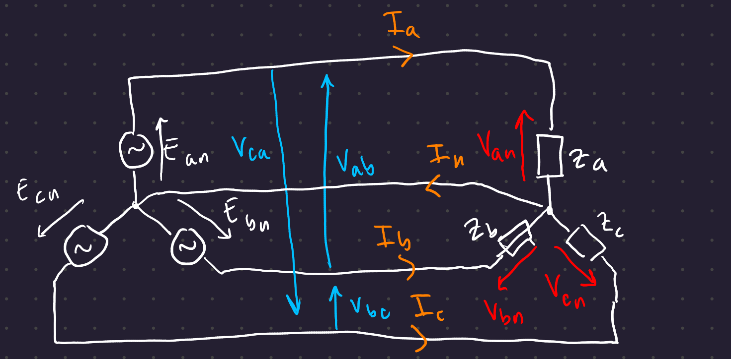
To find the line voltages, use Kirchoff’s Voltage law: V_{ab} = V_{an} - V_{bn} on the phasor diagram:
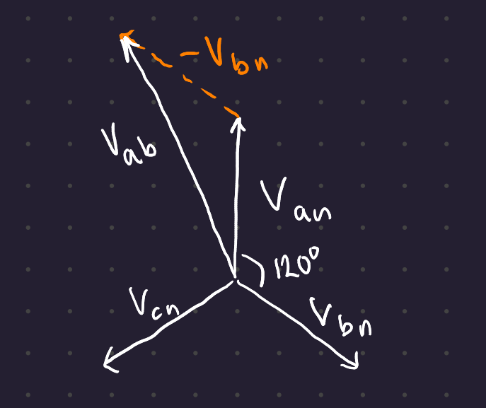
Therefore V_{ab} = \sqrt{3} \ V_{an}
The line voltage leads the phase voltage by 30°, and the magnitude of the line voltage is \sqrt{3} times the magnitude of the phase voltage.
3.3 Delta Connection
With a delta load, there are only line voltages.
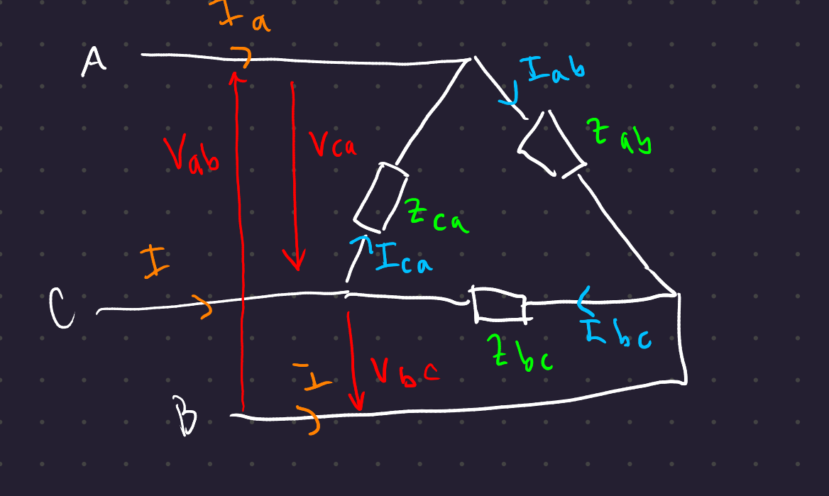
By KCL, the line current I_a = I_{ab} - I_{ca}
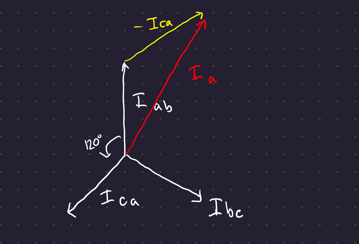
Therefore line current = \sqrt{3} times the phase current, and lags the phase current by 30° for a delta system.
Generally, in three-phase power, you only talk about line voltages, not phase voltages. Just like how you assume voltage is RMS, you talk about 400V three phase systems and 230V single phase systems - even though the phase power in both is the same.
4 Power in 3-phase systems
4.1 Star
The total power in a star system is the sum of the powers in the 3 branches, as fouund by P = VI.
Recall that single phase power is |V_{rms}|\ |I_{rms}| \ \cos (\phi_V - \phi_I)
So in a tthree-phase star system, P = |V_{an}| \ |I_a| \cos(\phi_a) + |V_{bn}| \ |I_b| \cos(\phi_b) + |V_{cn}| \ |I_c| \cos(\phi_c)
In a symmetrical system Z_a = Z_b = Z_c, all \phi are equal. This \phi is the power factor angle, equal to the angle of the phase voltage minus the angle of the line voltage (\Phi_{V_{phase}} - \Phi_{V_{line}})
So
P = 3 \ |V_{phase}| \ |I_{phase}| \cos \phi
Recall that the phase current is the line current, and the phase voltage is the line voltage over \sqrt{3}.
P = \sqrt{3} \ |V_{line} | \ |I_{line}| \cos (\phi)
4.2 Delta
The power in one load is |V_{line}| \ |I_{phase}| \ \cos (30°), so the power is the same as in the star-connected configuration.
P = \sqrt{3} \ |V_{line}| \ |I_{line}| \cos (\phi)
All you need to know to work out the power dissipation in a 3-phase system are the line current, the line voltage, and the power factor angle.
5 Comparison of Star and Delta
As long as the loads are balanced, you can analyze a single phase and easily extrapolate to all three phases.
| Star | Delta | |
|---|---|---|
| Voltage | \|V_{line}\| = \sqrt{3} \ \|V_{phase}\| V_{line} leads V_{phase} by 30° | Line voltage only |
| Current | I_{line} = I_{phase} | \|I_{line}\| = \sqrt{3} \ \|I_{phase}\| |
Power:
\begin{align} |S| &= \sqrt{3} \ |V_{line}| \ |I_{line}| \\ P &= \sqrt{3} \ |V_{line}| \ |I_{line}| \cos (\phi) \\ Q &= \sqrt{3} \ |V_{line}| \ |I_{line}| \sin (\phi) \end{align}
The power of a system with voltage phasor V_{line} and power phasor I_{line} is simply the dot product V_{line} \cdot I_{line}
The power factor angle is the angle of impedance, which is going to be the phase diffference between voltage and current. \phi = \phi_V - \phi_I, so \phi = \phi_Z.
This power factor angle, in a star-connected system, is the angle between the phase voltage and the phase current.
6 Unbalanced Systems
Most high-power generators and loads use three phase power, and they all tend to be balanced across the three phases. Small loads, however, are typically connected to a single phase. With small power, there is no guarantee that the loads are going to be balanced across all three phases.
To mitigate current imbalances, a lot of houses are generally attached to a single phase (ie 12 on one phase, 12 on another phase, 12 on the third phase…) but of course you’re never going to fully balance loads on individual phases. You can have imbalances in current draw and voltage supply.
“Recall” that reactive power draw tends to cause voltage rises across power lines. So loads and voltages are going to be unbalanced.
In a star configuration with a neutral, if the loads are unbalanced, the neutral current will be non-zero. Then the problem devolves to three single-phase problems running in parallel.
In a star configuration without a neutral, or in a delta configuration the analysis is harder. Imbalanced loads in these scenarios cause imbalances in the line currents. This can generally be solved as a large system of simultaneous equations (linear algebra ftw.)
This is the reason domestic networks are (almost) always connected as a 4-wire system, so that your power is not affected by your neighbors’ usage.
7 Conclusion
Three phase systems are used in the generation, transmission and distribution of electrical power.
Large industrial loads are 3-phase balanced loads.