Basic Flow Fields and Phenomena
1 Laminar Flow

Laminar flow has smooth fluid motion in “layers” (laminae).
Reynold’s experiment (after 19th centure Manchester professor). The experiment involves creating dye lines at different flow speeds. With a low flow speed, the dye line is straight and parallel, and remains clearly defined through the length of the pipe. With a faster flow speed, the dye line starts to break up and eventually engages in runaway disturbances (turbulent state): the dye line breaks up into a myriad of entangled threads.
The transition from laminar to turbulent flow is quite abrupt.
2 Turbulent Flow
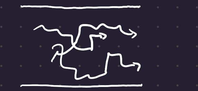
There is still a net flow, but now there’s a lot of 3d random motion as well, which creates a very unstable regime.
3 Reynolds number
Re \equiv \frac{\rho u D}{\mu} \tag{1}
Ratio of the inertial, or disturbing forces (\rho, u, D) to the viscous forces (\mu).
For flow in a pipe: - Re < \approx 2000 creates laminar flow (if undisturbed) - Re > \approx 4000 creates turbulent flow - 2000 < Re < 4000 is transitional flow: it could be either laminar or turbulent, but you can’t tell from the Reynold’s number alone.
At a low Re, viscous forces dominate. At high Re, viscous forces become negligible.
These numbers only apply for flow in a pipe. Other values must be taken for other flow situations.
4 Flow in a pipe
Near the walls of the pipe, the fluid shears and the velocity drops. This is the boundary layer. At the walls, you have the no-slip condition from earlier. In the boundary layer, viscous effects dominate.
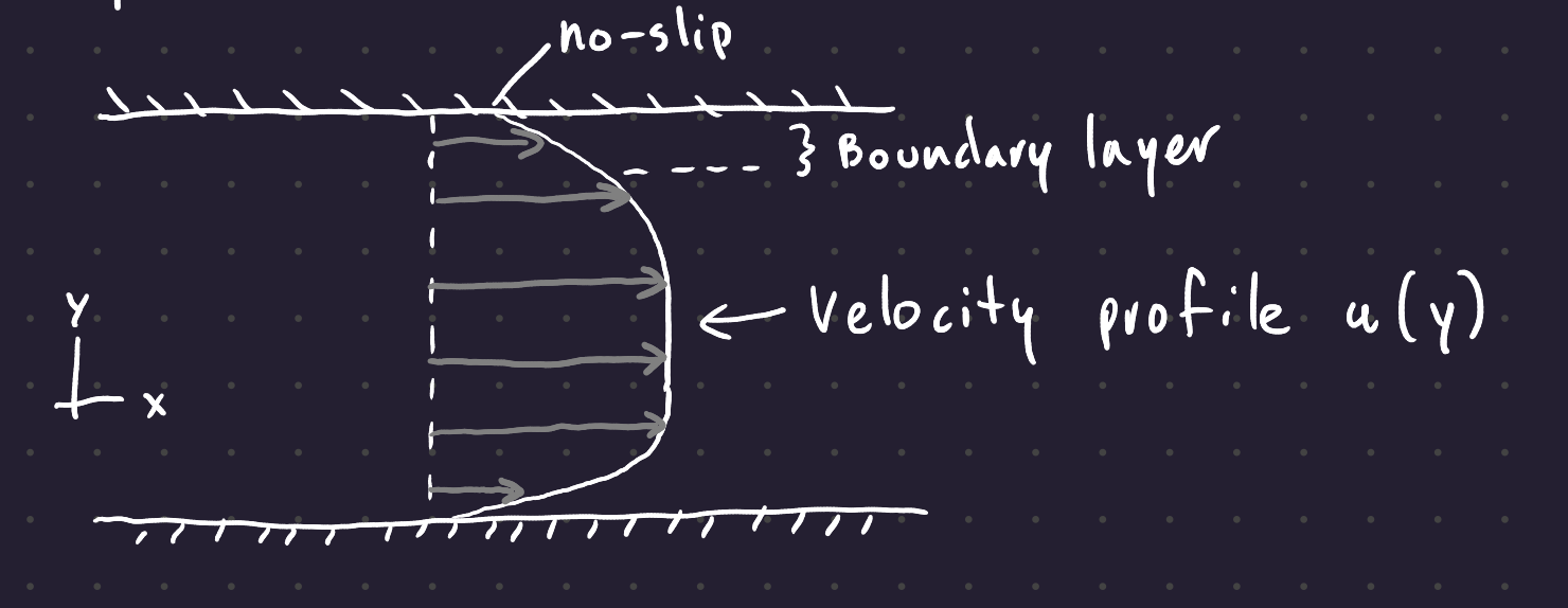
The boundary layer thickness (\delta) is greater for more viscous fluids, lesser with higher flow rates, and increases as you move down the pipe.
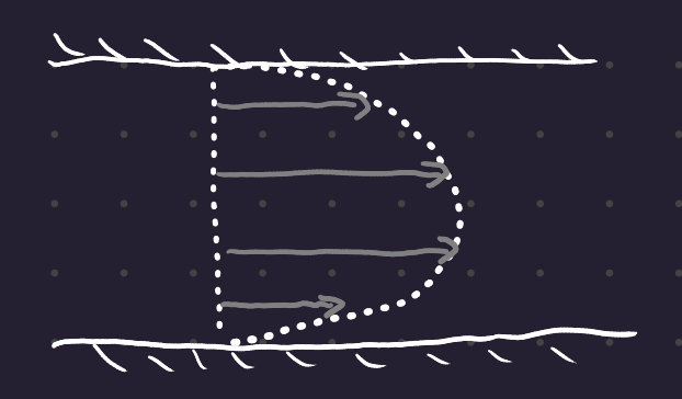
The variation of u (flow speed) with the cross-duct position y is the velocity profile u(y).
With laminar flow, u(y) creates a parabola.
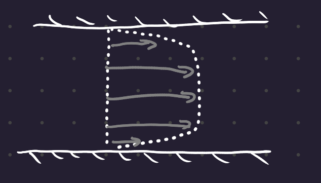
With turbulent flow, between the boundary layers, there is a roughly flat profile. The fluid within the pipe is mixed, and the momentum of the fluid is evenly distributed beyond the boundary layer.
4.1 Ideal Fluid
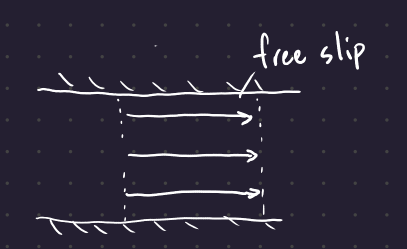
An ideal fluid is incompressible and inviscid, ie has no viscosity. Since there’s no shearing, the flow in the pipe is uniform with respect to y.
5 Flow Past a Bluff Body
Bluff: The opposite of streamlined.
There are 5 regimes of flow, corresponding to different Reynolds numbers.
The Re number is now partly determined by the size of the cylinder - the characteristic length will be the diameter of the cylinder.
5.1 5 regimes
5.1.1 Ideal - Flow attached
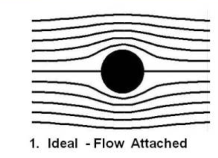
Here the reynolds number is very low (under 0.1 or so). Here the flow is streamlined, where no flow crosses a streamline. The flow absolutely follows the geometry.
5.1.2 Separated - steady
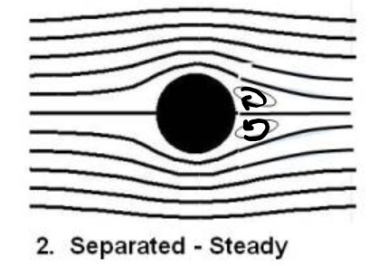
Here the reynolds number is slightly higher - from 1 or 2 to perhaps a few 10s. The flow has separated from the cylinder on the far side of the flow, creating two recirculating regions of fluid.
5.1.3 Unsteady - oscillating
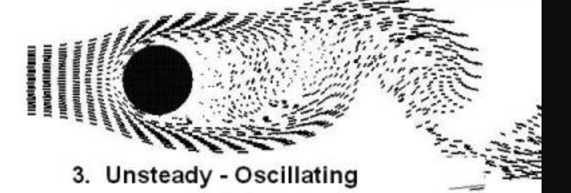
In this case, the flow separates, departing from the geometry of the cylinder. Downstream of the cylinder, there’s a wake. Vortices are shed alternately off the top and the bottom of the cylinder.
5.1.4 Laminar - Separated
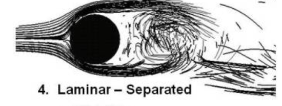
Instead of the beautiful vortex shedding, you get a simple mess. The wake behind is unstructured and messy.
This occurs for 20,000 < Re < 100,000.
5.1.5 Turbulent - Separated
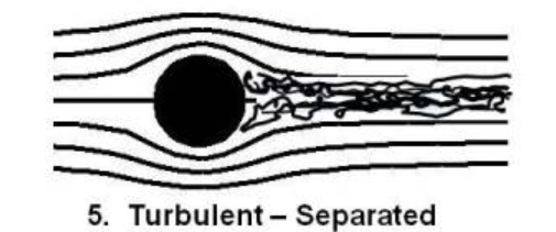
The separation point is now further to the rear of the cylinder, occuring at the upper end of engineering flows. The boundary layer around the cylinder is turbulnent, allowing the stream to follow the cylinder further to the rear than the laminar layer.
Re > 200,000
5.2 External Flow
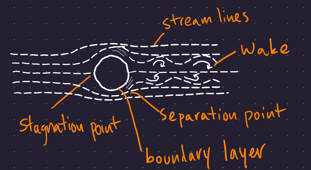
There are 3 main flow regimes:
- The “Free Stream” has largely undisturbed flow
- Adjacent to the body is the boundary layer flow
- The stream shears within this region due to adhesion to the wall.
- Separated regions - the wake, where the boundary layer has separated from the surface of the body. These tend to have recirculating water.
5.3 Drag
General term for force on a body in a downstream direction.
Flow past a bluff body results in “form drag”, rather than skin-friction drag.
This is created by - Recirculation in wake (lots of viscous friction caused by shearing particles) - Energy losses in wake due to viscous friction, causing the pressure in the wake to drop - The fluid slowing in front of the stagnation point causes the pressure in front of the body to increase.
These pressure differences (enhanced zone in front of the body, decreased pressure to the rear of the body) create a net force on the body from its front to its back. To find the force, multiply the pressure by the area of the bluff body.
To streamline, reduce the area of the wake, reducing the area for the pressure difference.
5.3.1 Drag force equation
F_D = \frac{1}{2}C_D \rho A u^2
F_D is the form drag of the body. C_D is the drag coefficient, particular to the geometry of each separate body. u is the velocity of the fluid (in the undisturbed stream), \rho is the mass density, A is the area of the body.
Different C_D:
- older car: \approx 0.6 to 0.8
- modern car: \approx 0.25
- racing car: \approx 0.18
The object size is accounted for by A, the projected frontal area of the object.
[Drag force chart]
Dotted line is a cylinder,
For very low Re, the drag force decreases as Re increases. From an Re of several hundred to an Re of several hundred thousand, the drag coefficient is pretty much flat at \approx 1 to 1.2. This is because the flow is separating at roughly the same place. At the low end, you have the pretty Von Karman wake, and at the high end a less pretty wake, but the fluid separates at the same place.
The “drag crisis” point where the drag drops precipitously corresponds to the point where the bluff body becomes more streamlined, with a narrower wake due to the turbulence in the fluid. Since the wake is smaller, the pressure - induced drag is reduced (acting on a smaller area).
5.4 Vortex Shedding
For long, slender bodies like cylinders, wake oscillates. At a lower Re, you have two recirculating regions, then at a higher Re you see one of those vortices begin to “win”, eventually fall off and start to trade off with each other.
Vortex shedding creates transverse lift forces, perpendicular to the flow of the liquid. Since the flow oscillates, the transverse lift forces also oscillate, potentially causing a ringing motion.
With a half cylinder, the separation is quite strong, and so the vortex shedding is even more intense.
5.4.1 Vortex shedding formula
\frac{fD}{u} \approx 0.198\left(1 - \frac{19.7}{Re} \right) \approx 0.2
\frac{fD}{u} is the Strouhal number St for a cylinder, where f is the frequency in Hz at which vortices are shed, D is the cylinder diameter in meters, and u is the free stream flow speed in meters per second.
The formula applies for 250 < Re < 2\times 10^5. Since Re is so small, the RHS may easily be approximated to 2 for large Re.
6 Flow Along a Flat Plate
And how it leads to skin friction drag
The flow visualizations in the old videos are created through the hydrogen bubble technique, which basically just means placing a thin piece of wire as a continuous electrode off of which tiny hydrogen bubbles continuously flow. Very cool.

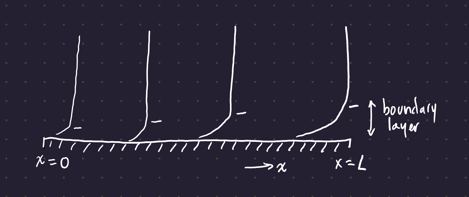
Before the flow reaches the plate (in the free stream) it feels no effect, but as soon as it hits the plate a no-slip condition forms, creating a boundary layer whose thickness increases as the flow travels further along the plate. Within the boundary layer, viscous effects are dominant; without the bounddary layer the flow is inviscid; there is no shear between the layers of the fluid.
6.1 Boundary Layer
The boundary layer thickness \delta is equivalent to the distance away from the wall (the y-distance) at which the flow speed u reaches 99% of the undisturbed (free stream) flow speed u_{\infty}. This is the velocity definition of the boundary layer.
The boundary layer flow may be either laminar or turbulent
6.2 Reynolds number on a flat plate
Here, the Reynolds Number Equation 1 is defined with respect to the characteristic length x, that is, the distance along the plate which the fluid has travelled.
Re_x = \frac{\rho u_\infty x}{\mu} = \frac{u_\infty x}{\nu} {eq-reynolds-plate}
As before, Re_x indicates whether to expect laminar or turbulent flow. On a flat plate, the flow is laminar when Re_x < 10,000, and the flow is turbulent above around Re_x > 20,000.
When the flow is laminar, the boundary layer thickness \delta is equal to
\delta = \frac{5x}{Re_x^{1/2}},
which means that \delta \propto \sqrt{x} (since Re_x \propto x), and \delta \propto \frac{1}{\sqrt{u_\infty}} (since Re_x \propto u). That is to say, the boundary layer increases with the square root of the distance from the leading edge, and the boundary layer thickness increases with one over the square root of the free stream velocity.
When the flow is turbulent, the relationship to Re_x is much weaker:
\delta = \frac{0.37 x}{Re_x^{1/5}}
The boundary layer thickness with turbulent flow increases with x^{4/5}, and it increases with 1/(\sqrt[5]{u_\infty})). This is much closer to a straight line in x.
6.3 Skin Friction Drag
The shearing on the plate induces a force in the direction of flow. Conversely, if you attempt to move an object through flow, you experience the same retarding force in the opposite direction of the motion of the body. This is skin friction drag.
Recall that the form drag force on a cylinder created by the pressure differential on either side of the cylinder was given by
F_D = \frac{1}{2}C_D \rho A u^2
This drag is created by surfaces perpendicular to the direction of flow. Skin friction drag, on the other hand, is created by surfaces tangent to the direction of flow. The equation for skin friction drag is
F_D = \frac{1}{2} C_f \, \rho \, A \, u_\infty^2
Here the drag is created by the area of the which is actually in contact with the fluid.
6.3.1 Skin Friction Drag Coefficient
C_f is the skin friction drag coefficient, which has different values for turbulent and laminar flow:
In laminar flow,
C_f = \frac{1.4}{Re_x^{1/2}}
In turbulent flow,
C_F = \frac{0.074}{Re_x^{1/5}} .