Stress Analysis
Stress, Mohr’s Circle, Triaxial Stress States, Uniformly Distributed Stresses, Elastic Strain, Stress-Strain Relations, Shear and Moment
1 Stress
It’s not just what you feel when you’re 10 days behind in your lectures, desperately struggling to catch up. Stress is a force per unit area. In a differential material element, the stresses may be characterized as a tensor:
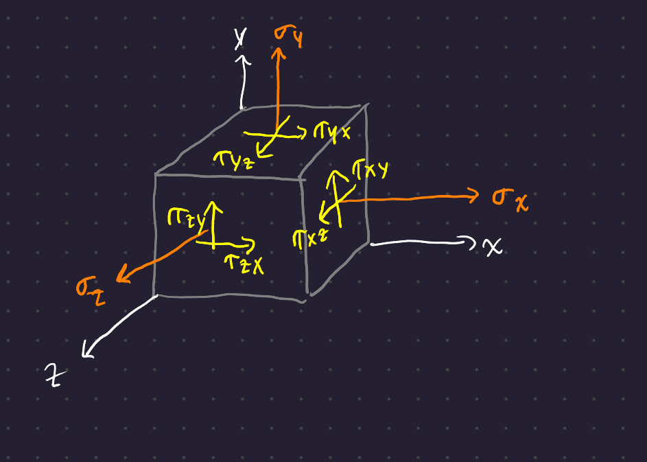
The subscripts on the normal stresses \sigma_x, \sigma_y, \sigma_z refer to the axis those stresses lie parallel with. The first subscript on the shear stresses \tau refers to the face along which that stress lies, and the second subscript indicates the direction along that face.
Since the element is in static equilibrium, the moments created by the stresses acting on each face of the element must cancel each other out. Therefore,
\tau_{yx} = \tau_{xy} \hspace{2em} \tau_{yz} = \tau_{zy} \hspace{2em} \tau_{zx} = \tau_{xz} \hspace{2em}
Tensile stresses are positive stresses, and shear stresses are positive if they act in the positive direction of a reference axis (arrows point in the positive direction in the diagram). The negative faces of the shear stress component have shear stresses actign in the opposite direction; these are also positive.
It’s more usual to see a 2D “slice” of a shear stress component:
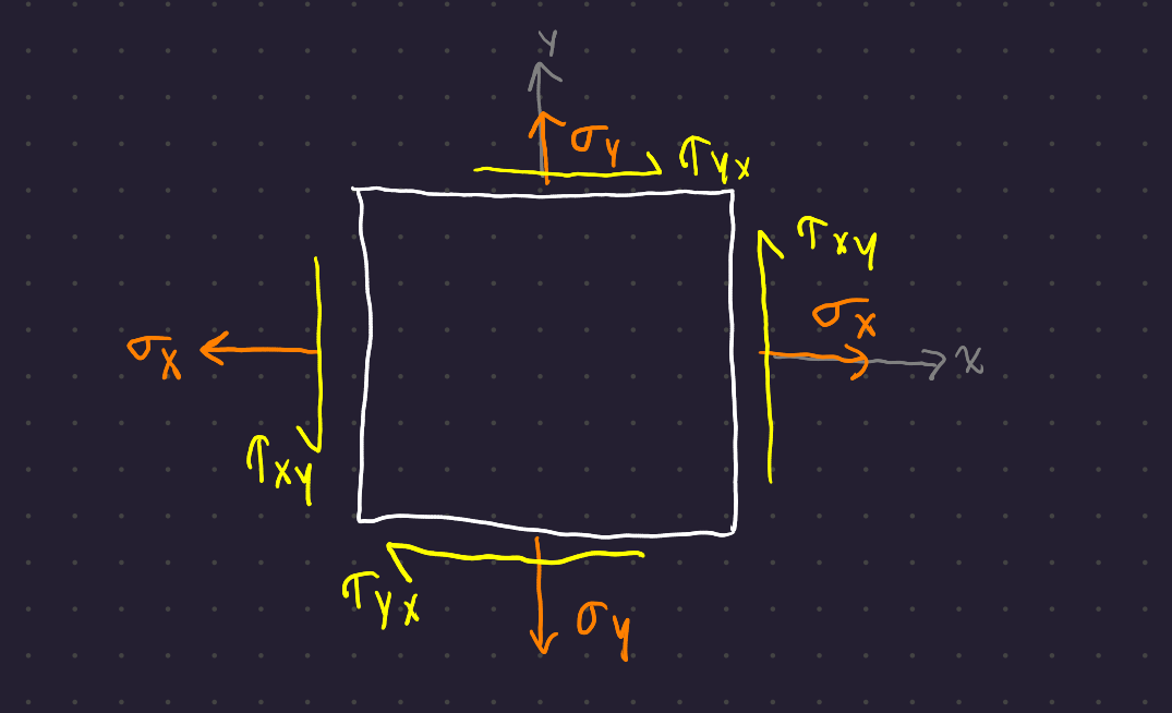
The sense of the shear components is specified by the clockwise or counterclockwise convention: \tau_{xy} is ccw and \tau_{yx} is cw.
2 Mohr’s Circle
If you cut the 2d shear component ?@fig-2d-shear with an oblique plane at angle \phi to the x-axis, you see resultant shears \sigma and \tau acting on the cut plane.
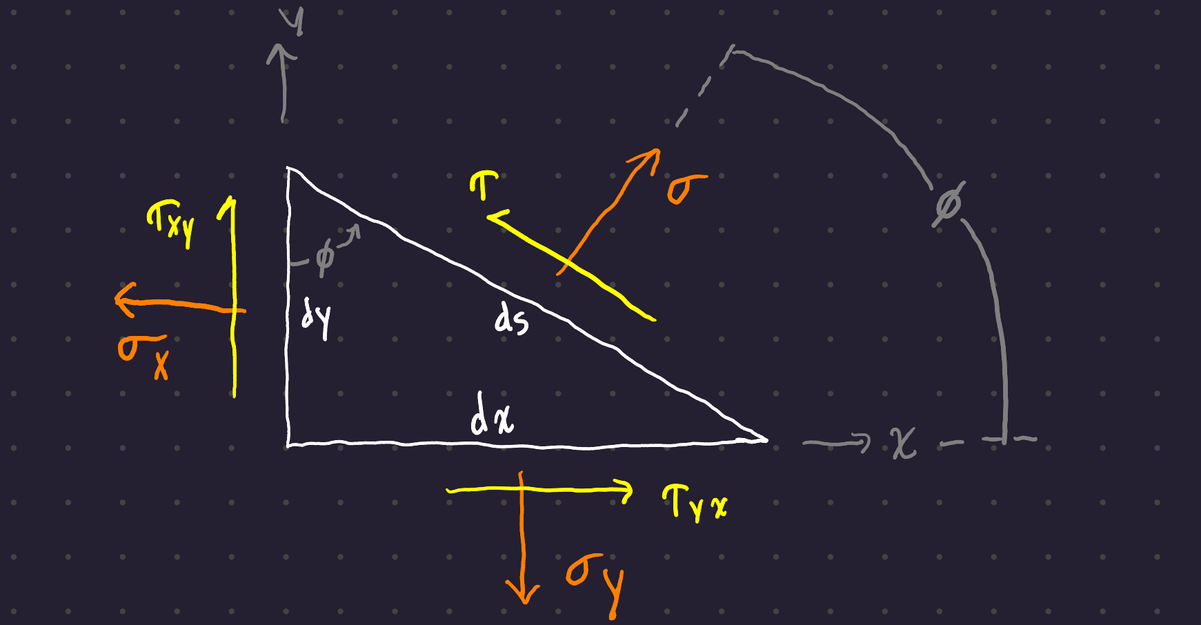
Assuming a unit cross-section, you can sum the forces to 0 (take the components of the face normal and shear stresses parallel to the plane through which the stress component is cut) and get the normal stress acting on the cut plane:
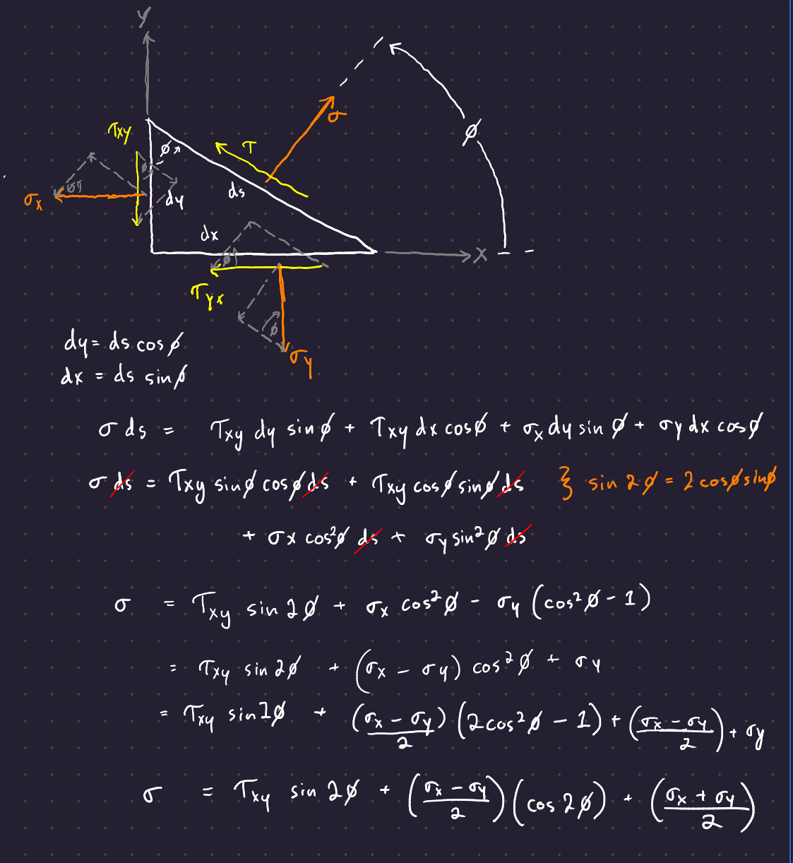
And the same for the plane shear stress:

Shigleys is incorrect. The tau shear term should have negative \frac{\sigma_x - \sigma_y}{2}\sin 2\phi, not positive. This is why it pays to go through the derivations yourself!
Further, you can notice that these equations parameterize a circle around the point (0, \frac{\sigma_x + \sigma_y}{2}) with respect to theta.
All in all, here are the equations for the shear stress and the normal stress on a plane at angle \phi to the x-axis:
\begin{gather} \sigma = \frac{\sigma_x + \sigma_y}{2} + \frac{\sigma_x - \sigma_y}{2}\cos 2\phi + \tau_{xy} \sin 2\phi \\ \tau = \frac{\sigma_x - \sigma_y}{2} \sin 2\phi + \tau_{xy} \cos 2\phi \end{gather}
To find the minima and maxima, differentiate the functions with respect to \phi and set the result equal to zero:
\tan 2\phi = \frac{2\tau_{xy}}{\sigma_x - \sigma_y} \tag{1}
Remember, All Stuy Teams Cheat. The values of the tangent of an angle repeat as you go around a circle!
At the two points where Equation 1 applies, the normal stresses reach a minimum and maximum. Those two stresses are the principal stresses, and the directions in which they act are the principal directions. The angle between the principal directions is 90°.
In a similar manner, you can differentiate the equation for shear stress to find the minima and maxima:
\tan 2\phi = - \frac{\sigma_x - \sigma_y}{2\tau_{xy}} \tag{2}
The angles of 2\phi where Equation 2 obtains are the values where the shear stress reaches its extremes.
By rearranging Equation 1 and plugging into the equation for \tau, it can be shown that there is no shear stress acting on the plane in the principal directions. The normal stresses acting at the maxima of the shear stresses are
\sigma = \frac{\sigma_x + \sigma_y}{2},
in other words, the average of the normal forces in the x and y directions. The normal stresses associated with the directions of the two maximum shear stresses are equal.
2.0.1 Formula for the principal shear stresses
\sigma_1,\, \sigma_2 = \frac{\sigma_x + \sigma_y}{2}\pm\sqrt{\left( \frac{\sigma_x - \sigma-y}{2} \right)^2 + \tau_{xy}^2}
2.0.2 Diagram
The Mohr’s Circle diagram is an effective graphical representation of the stress state at a point.
Create a coordinate system with normal stresses on the x-axis and shear stresses on the y-axis. Tensile normal stresses are plotted to the right of the origin and compressive normal stresses are plotted to the left. Clockwise shear stresses are plotted up on the y-axis, and counterclockwise shear stresses are plotted down.
Plot Mohr’s circle from the stress state by laying off \sigma_x as OA, \tau_{xy} as AB, \sigma_y as OC, and \tau_{yx} as CD. The line DEB is the diameter of Mohr’s circle with center at E on the \sigma axis.
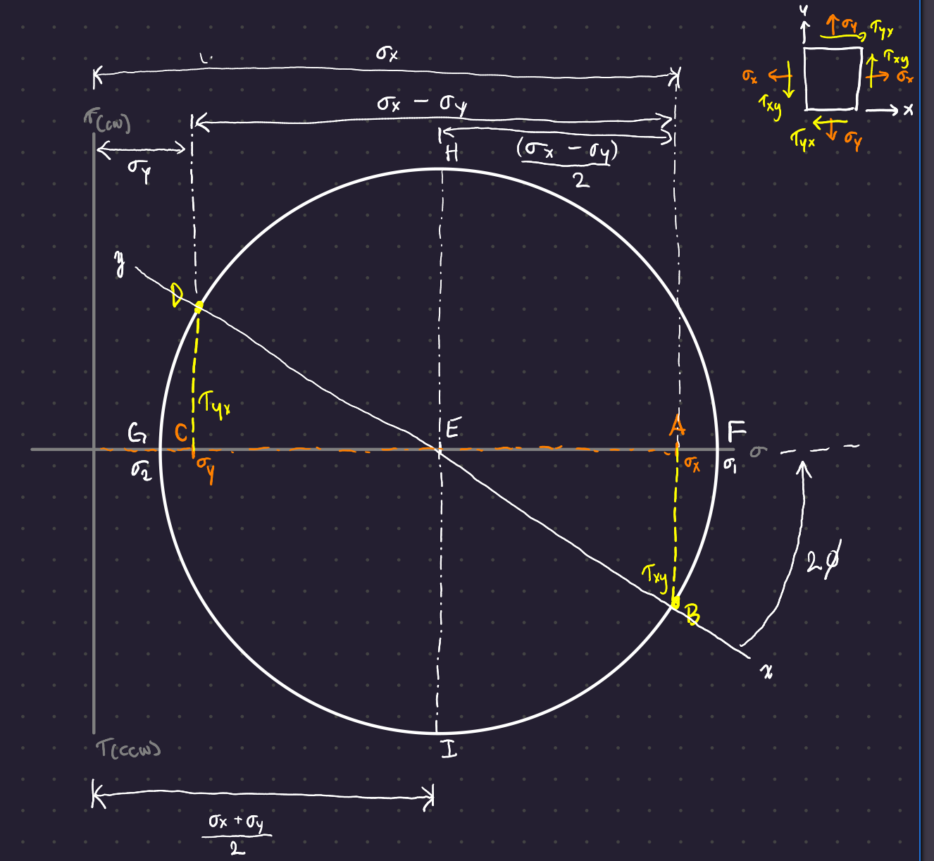
Point B represents the stress coordinates (\sigma_x, \tau_{xy}) on the x faces, and point D represents the stress coordinates (\sigma_y, \tau_{yx}) on the y faces. Point F is the location of the maximum normal stress, and the angle from the xy-line to the abscissa is 2\phi. Point G is the location of the minimum normal stress. The maximum shear stress occurs at points H and I.
The key thing to note here is that one full rotation around the circle equals a physical stress-element rotation of 180°. This is why the other side of the x-y line represents the stresses on the face at 90° to the x face.
When plotting Mohr’s circle, remember that clockwise shear is positive and counterclockwise shear is negative - the opposite of the normal angle convention! Also, rotations in physical space result in rotations in the same direction in Mohr’s circle space.
3 Triaxial Stress States
As with the two-dimensional case, there is a particular orientation of the stress element for which all shear-stress components are zero. When an element has this orientation, the normals to the faces are the principal stresses. The process involves finding the three roots to the cubic:
\begin{gather} \sigma^3 - (\sigma_x + \sigma_y + \sigma_z)\sigma^2 \\ + (\sigma_x\,\sigma_y + \sigma_x\,\sigma_z + \sigma_y\,\sigma_z - \tau_{xy}^2 - \tau_{yz}^2 - \tau_{zx}^2)\sigma \\ - (\sigma_x\,\sigma_y\,\sigma_z + 2\tau_{xy}\,\tau_{yz}\,\tau_{zx} - \sigma_x\,\tau_{yz}^2 - \sigma_y\,\tau_{zx}^2 - \sigma_z\,\tau_{xy}^2) = 0 \end{gather}
4 Further Notes about Mohr’s Circle:
The principal stresses can also be found by diagonalizing the stress matrix \sigma:
\begin{align} \bf \sigma &= \begin{bmatrix} \sigma_{xx} & \sigma_{xy} \\ \sigma_{yx} & \sigma_{yy} \end{bmatrix} \\ &= \bf{\Sigma \Lambda \Sigma^{-1}} \end{align}
Then the values of the principal stresses are the eigenvalues of the stress matrix. Mohr’s circle is a shortcut to finding these eigenvalues for a symmetric stress matrix.
Note - Von Mises Stress
5 Uniformly Distributed Stresses
Stress is often assumed to be uniformly distributed, resulting in pure tension, pure compression, or pure shear.
Take for example a tension rod: You pull a rod evenly between two pins with a force F. If you make a cut somewhere along the rod, the force acting on that cut surface should be \sigma A.
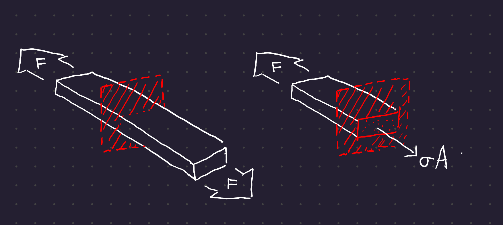
For uniform stress to hold:
- The bar must be straight and homogeneous
- The line of action of the force must coincide with the centroid of the section
- The section must betaken remote from the ends and remote from any discontinuity or abrupt change in cross section.
The same holds for compression, although caution should be taken placing slender bars in compression (they may fail by buckling.)
6 Elastic Strain
When a straight bar is loaded in tensile stress, it elongates. The amount of elongation is called strain. The elongation per unit length of the bar (dimensionless quantity) is called unit strain. These terms may also be referred to as total strain and strain respectively.
Strain is calculated as
\epsilon = \frac{\delta}{l}
where \delta is the total strain of the bar within the length l.
6.1 Shear Strain
Shear strain is denoted by \gamma, and refers to the change in a right angle of a stress element subjected to pure shear.
+----------+
| no shear |
+----------+

  +----------+
 / sheared  /
+----------+  <- γ
When stress is proportional to strain,
6.2 Constants of proportionality
\sigma = E \ \epsilon \hspace{2em} \tau = G \ \gamma
The constant E is the modulus of elasticity, and the constant G is the modulus of rigidity, or the shear modulus of elasticity.
When a bar is subject to axial loading only, it squishes or stretches a bit, causing some lateral strain. These strains are proportional to each other in the elastic region.
\nu = - \frac{\textnormal{lateral strain}}{\textnormal{axial strain}}
\nu is Poisson’s ratio.
The three elastic constants are related to each other:
E = 2G (1 + \nu)