Assignment 1
Photograph a Structure


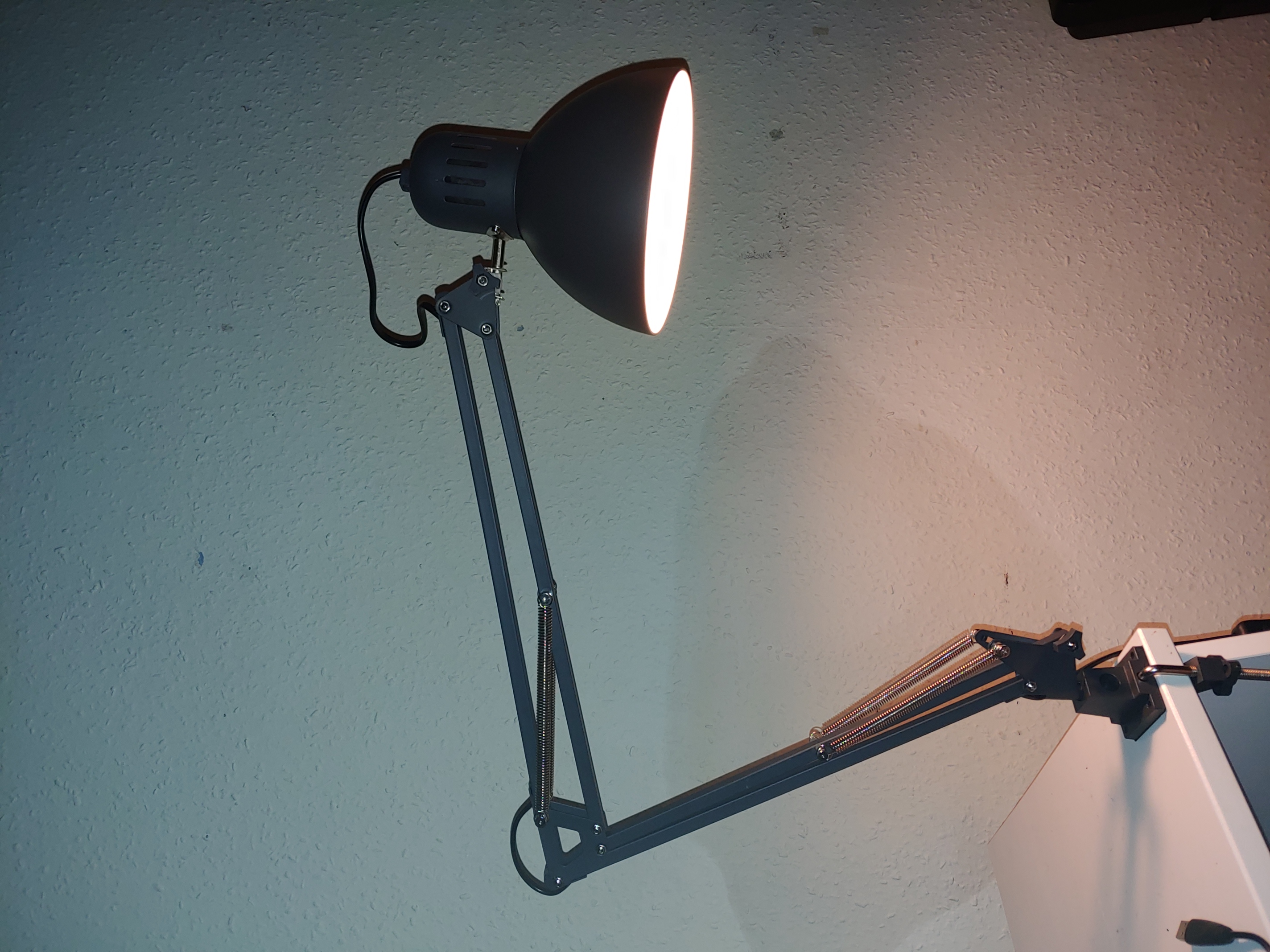
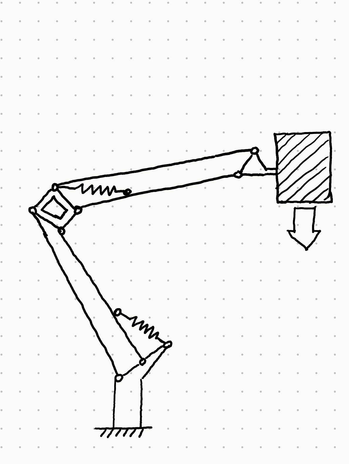
The lamp is represented from the side to give the best view of the armatures. The only joint which is not represented in this view is the connection between the body and the head of the lamp, which is a universal joint held in place by friction. Since it’s held in place by friction rather than a balance of forces in beams or trusses, this joint does not fit naturally into a structural diagram, and so its omission is acceptable.
The base of the lamp is represented as a fixed support, since the lamp is clamped to the table. The bottom part of the lamp is represented as a beam, since it must withstand both axial and bending moments. Every joint in the diagram represents an actual pinned joint which can rotate. The arms of the lamp are represented as struts; since they pinned on both ends, it is not possible for them to transmit bending forces. (This is not strictly true for the struts with the springs attached in the middle; one could defensibly have drawn those as beams since the springs create a slight bending moment in those supports). The springs are drawn as springs but could just as easily have been drawn as struts, since they carry only axial loads.
Drawing the diagram gives a good idea of how the lamp retains its form throughout the range of motion. The pinned struts keep each section parallel (they form a parallelogram with the beam-like structures at either end), and the springs (along with some friction in the pinned joints) retain the shape of the structure through its motion.