DC Machines
The simplest machines are mechanically switched DC machines, where the changing electric current is created by brushes running around a commutator.
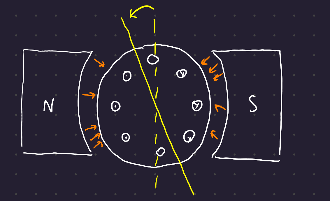
Such a machine is best characterized by considering a single loop of wire rotating through a stationary magnetic field:
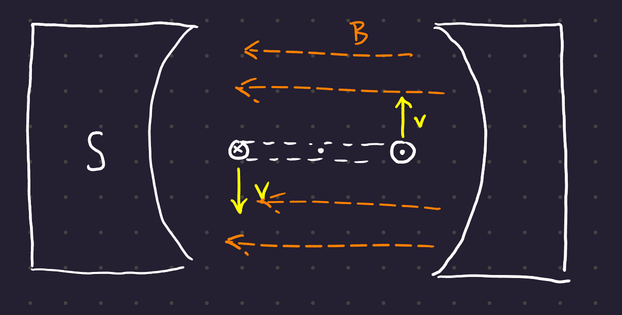
As the coil rotates through the field, a voltage is induced. By Faraday’s laws, the induced current is the cross-product of the velocity vector and the magnetic field, projected onto the wire:o
e_{ind} = (\textbf{v} \times \textbf{B}) \cdot \textbf{l}
By the RHR for cross products (thumb goes in the direction of resultant when the fingers coil in the direction of the second vector from the direction of the first) the induced voltage is positive out of the page on the right hand side, and positive into the page on the right hand side.
In general, the voltage in any real machine depends on the same three factors:
- The flux in the machine
- The speed of rotation
- A constant representing the construction of the machine
Now consider what happens when you apply an external current to the rotating loop of wire.
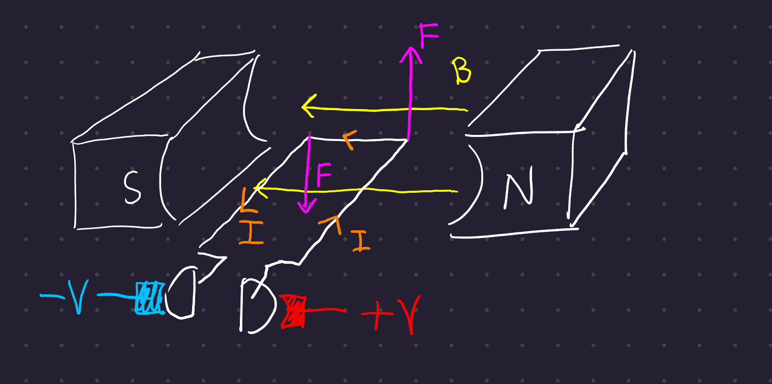
Again applying Faraday’s laws, there’s a resultant force acting on the wire, given by the cross product of the length of the wire in the direction of current and the magnetic field:
\bf{F_{ind}} = \textit{i}(\bf{l} \times \bf{b})
This force always points perpendicular to the magnetic field, so the torque created by the force is usually misaligned with the center of the rotor. This causes the machine to lurch with a single coil. By adding more poles and more coils, the response of the machine is made smoother.
Generally, the torque in any real machine depends on the same three factors:
- The flux in the machine
- The current in the machine
- A constant representing the construction of the machine
(Note the difference in factor #2 between the voltage and the torque induced in machines!)
In unloaded conditions, the machine gathers speed until the induced current in the coils equals the driving voltage (they cancel each other out). When you add a load to the shaft, this causes the speed of the motor to drop. When the speed of the motor drops, the current running through the coils increases. This causes the torque generated by the coil to increase, until the machine finds a steady state again where the torque created by the coil equals the torque applied to the shaft.
If torque is applied to the shaft in the direction of rotation, this causes the voltage at the terminals to exceed the voltage applied by the battery, generating electrical power.
All else being equal, a weaker magnetic field results in a faster-spinning motor, since it takes a higher speed for the induced current in the wire to equal the driving current. If you completely lose a field, this can lead to a runaway condition and trip all your breakers!
1 Armature Reactions
So far we’ve considered the magnetic field of the stator, which induces rotation in the coil of the DC machine. However, the coils of the rotor can create their own magnetic field, which creates problems for our machine.
Definition 1 (Armature Reaction) The distortion of magnetic flux inside a machine created by induced magnetic field in the coils of that machine.
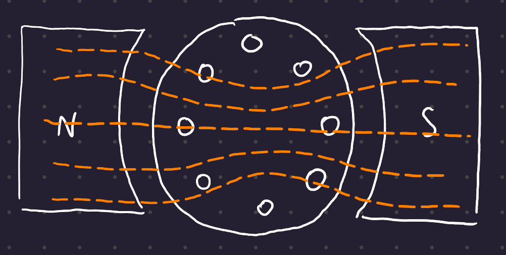
The first problem is neutral-plane shift. The magnetic neutral plane is the plane within the machine where the velocity of the rotor wires is parallel to the flux line, so that the induced voltage in the conductors in that plane is zero.
When there is no current in the armature, the neutral plane is perpendicular to the poles of the machine:
But as current starts to flow through the wires (recall that the machine here is a generator which is driving a load, and that the direction of rotation is CCW), the armature creates a magnetic field:
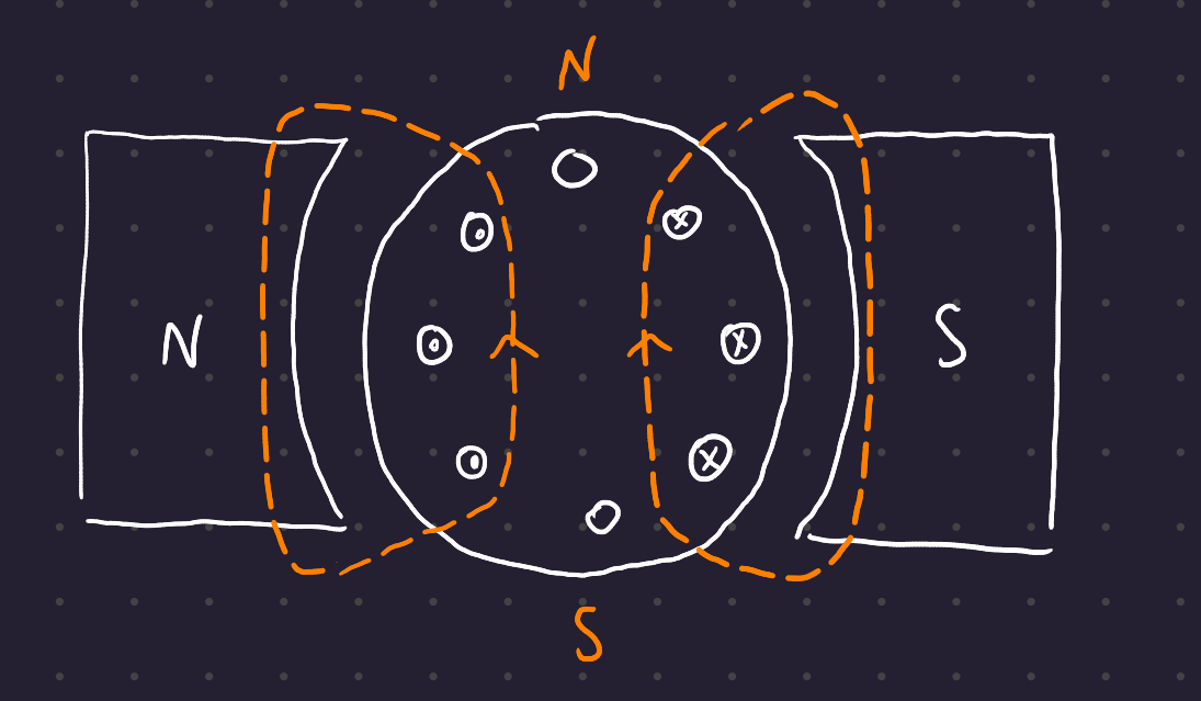
This magnetic field combines with the magnetic field of the stator, creating an offset field with a new neutral plane shifted in the direction of rotation:
If the machine had been run as a motor, the opposite effect would happen: the neutral plane would shift in the opposite direction to that of the direction of rotation.
Also note that the amount of shift depends on the current running through the coils of wire, and is thus variable based on loading conditions.
This is bad: the commutator needs to short out conductors only when the voltage between them is 0, and neutral plane shift affects where this zero-point occurs. The result is a current flow through the commutator, and arcing and sparking at the brushes.
Also notice that the motor is generally running at the kneepoint of the H-B graph, which means that the added magnetic fields add less flux than the subtractive fields take away, resulting in an overall weakening of magnetic field.
This flux weakening can create runaway conditions in shunt DC motors, where the weakening flux causes the speed to increase, resulting in an increased load, creating an increased armature current, and the ultimate destruction of the motor.
1.1 Inductive Kick
The voltage in the coils is constantly reversing, resulting in extremely high rates of current change di/dt.
Recall that inductance-induced voltage is related to the rate of current change:
v = L \frac{di}{dt}
With even a very small inductance L, this can result in massive induced voltages, and the same arcing and sparking from neutral-plane shift.
2 Generated Voltage Expanded
Earlier we said that voltage depends on flux \phi, speed \omega, and some constant depending on the construction of the macahine. Here we expand this derivation:
3 Configurations of DC Machines
There are three options for DC machines without permanent magnets. The armature refers to the coil which rotates, and the field refers to the stationary field in the stator.
| name | characteristic |
|---|---|
| separately excited | field and armature detached from each other |
| shunt connected | field and armature in parallel, same supply |
| series connected | field and armature in series, same current in each |
For a given electrical machine, we’re mainly interested in torque at different speeds.
3.1 Characteristic equations
Here are the key characteristic equations:
\begin{align} V_{DC} &= I_AR_A + E_A \\ E_A &= K \ \phi \ \omega \\ T &= K \ \phi \ I_A \end{align}
And assuming that the winding is not saturated, (\phi \propto I_F):
\begin{align} E_A &= K' \ I_F \ \omega \\ T = K' \ I_F \ I_A \end{align}
As long as the number of unknowns does not exceed the number of equations, they may be determined. Note that the K' term only appears in a coil whose response to mmf is linear.
This allows you to find equations for the various configurations of DC machines. The key is to see what determines the field current.