Introduction to Circuits
1 Course structure:
- Week 1-6: Electrical power engineering
- Technical & engineering aspects of ac power systems
- Week 7-10: Electrical Machines
- Electromagnetics, power trarnsformers, DC machines, 3-phase induction.
- Overhauled this year due to a new lecturer.
The course is 100% end-of-course exam plus a pass-fail wiring laboratory component.
Office hour: 14:10-15:00 Tuesdays
Weekly seminars: 15 students per group, work through targeted questions. Alrick classroom 14.
2 Laboratory:
Wiring + testing a power supply for a 3-phase induction motor. Starts in week 3, working in groups of 2.
Perform the preparatory material; do not fail the lab.
No PPE required.
Don’t forget to bring a bottle of water to the lectures. The room is very hot and dry.
3 Electrical Circuits
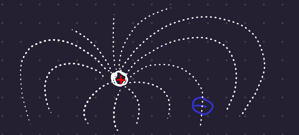
3.1 Electrical fields:
Generated by electric charges, exert forces on other charged particles.
Electric field strength is the force per unit charge that would be experienced by a test charge at that point.
Newtons / Coulomb.
3.2 Electric Potential:
How much work needs to be done to move a unit charge from one point in an electric field to a reference point (electric field strength is 0)
Measured in Joules per Coulomb (V).
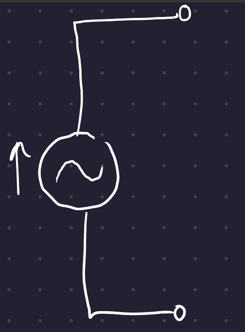
3.3 Voltage: Circuit symbols
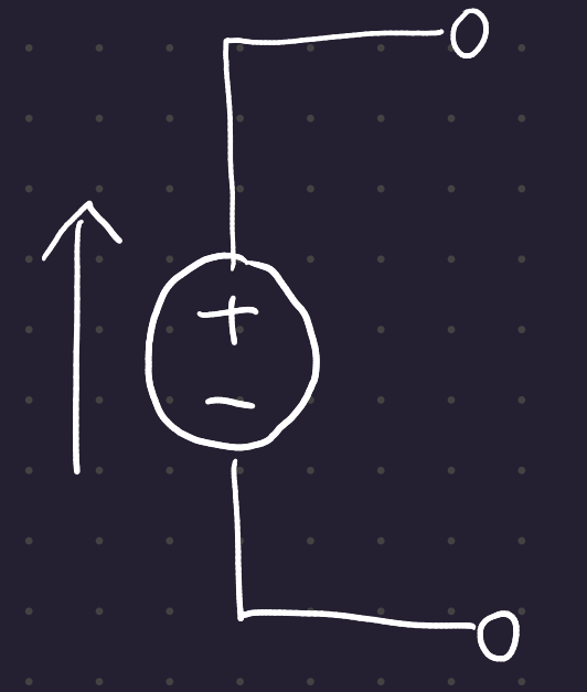
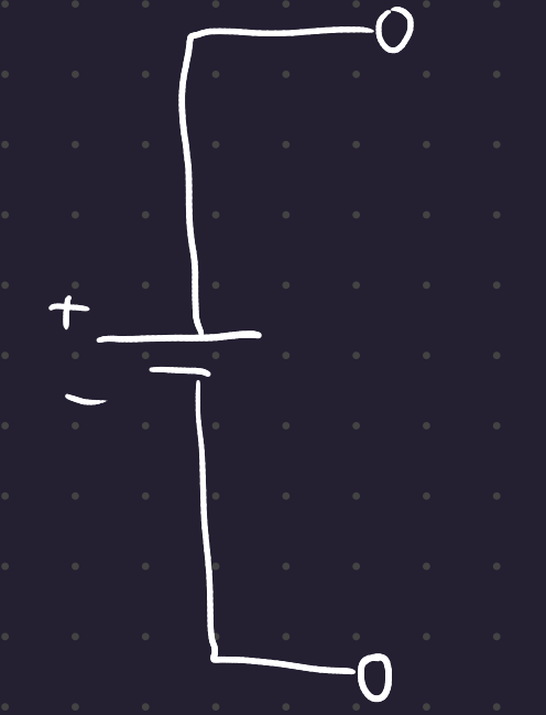
Above are 2 methods of denoting a DC circuit. AC circuits can be denoted as such:
3.4 Reference or Ground
One part of the circuit is denoted as ground. To refer to other voltages, you refer to the “voltage across X”.
3.5 Current
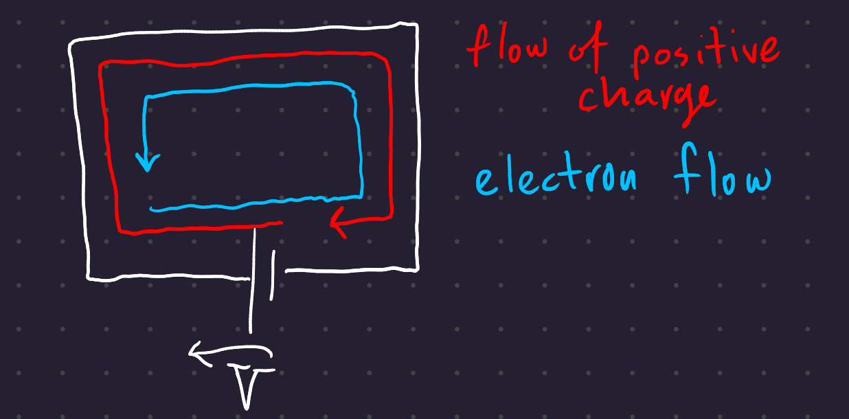
Rate of flow of positive electric charges through a conductor (ie the negative rate of electron flow). A voltage induces current flow.
Unit: Amps (A). Current is often denoted by I.
3.6 Resistance
Resistance is a measure of the opposition to charge presented by an object.
Ohm’s law:
V = IR
3.7 Power dissipation:
Power generated by an object is:
P = VI
V is Joules (J) / Coulomb (Q), and I is Coulombs (Q) / second (S), so power P is Joules (J) /second (S), ie Watts.
Power dissipation in a resistor:
\begin{gather} P = VI I = \frac{V}{R} P = \frac{V^2}{R} \end{gather}
4 Components
4.1 Resistors
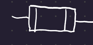
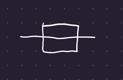
A resistor is a passive electrical component with an electrical resistance. The flow of current is equal to some constant times V.
Resistors are used to dissipate heat in a hurry (braking resistors on motors), or to model other components (like voltage lines.)
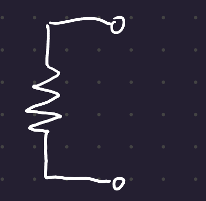
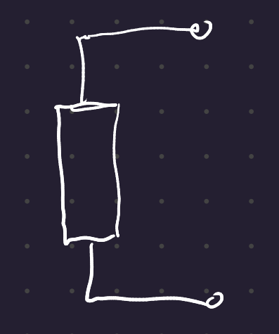
Resistors can be drawn two ways: specific and generic.
4.2 Capacitors
Two conductive surfaces separated by an insulating dielectric.
The current flow through a capacitor is proportional to the rate of change of voltage across the cap.
I = C \frac{dV}{dt}
C is the capacitance, in Farads.
Capacitors are often used as filters in electrical circuits to prevent the flow of DC current and smooth out spikes.
They play a very important role in power engineering.
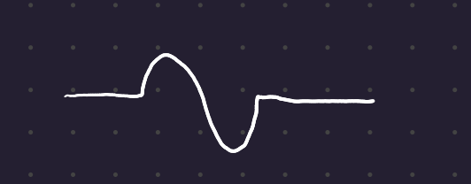
4.3 Inductors
Formed by winding a conductor around a core material (metal, air, steel)
V = L\frac{dI}{dt}
Where L is the inductance, measured in Henrys.
Often used as filters.
4.4 Fuses
Prevent current from passing above a certain amperage (thin wire which melts).
4.5 Use of components
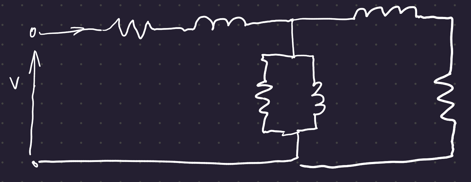
Capacitors, resistors, and inductors are used to develop models for larger, more complicated systems.
5 Circuit Analysis
5.1 Kirchoff’s Voltage Law:
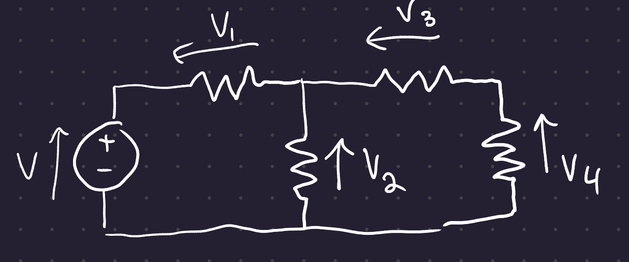
The sum of the voltages around any loop is zero
In other words, the sum of the current gains and the current drops around a loop is zero.
\begin{gather} V + V_1 + V_2 = 0 \\ V_2 + V_3 + V_4 = 0 \\ V + V_1 + V_3 + V_4 = 0 \end{gather}
5.2 Kirchoff’s Current Law:
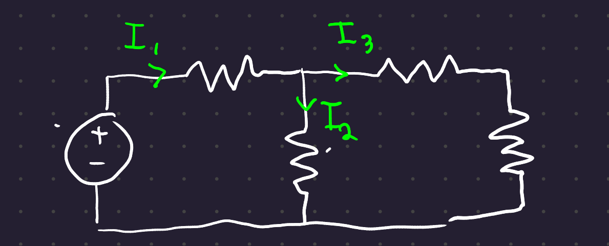
The sum of the currents flowing into a node must equal the sum of the currents flowing out of a node
I_1 = I_2 + I_3
These laws take very well to analysis through linear algebra.
5.3 Rules for reducing resistances to equivalent resistances:
Resistors in series add together:

R_{eq} = \Sigma_n R_i
Resistors in parallel add like so:
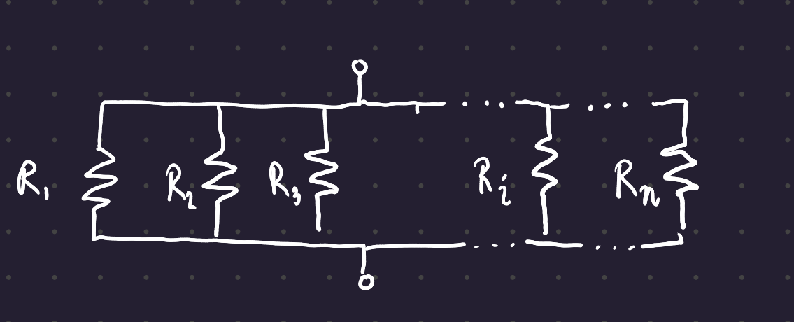
R_{eq} = \frac{1}{\Sigma_n \frac{1}{R_i}}
When you have a voltage divider, the following equation attains:
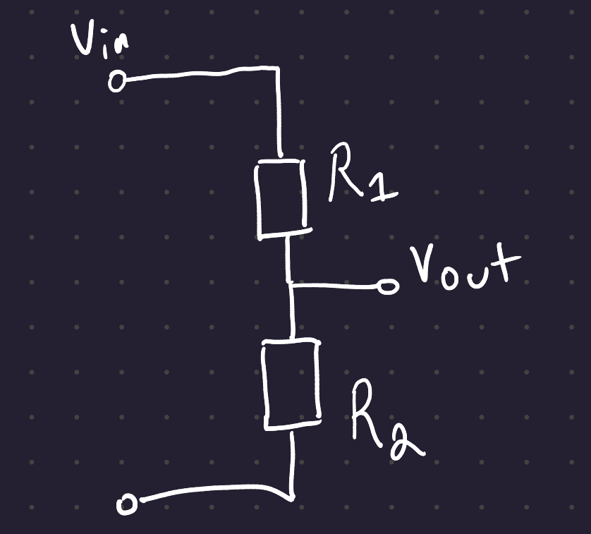
V_{out} = V_{in} \frac{R_2}{R_2+R_1}
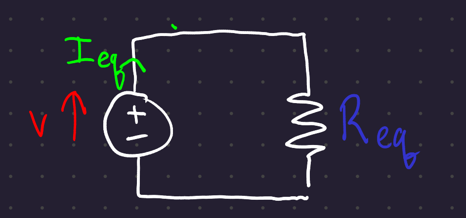
With these rules, you should be able to take any circuit (made up only of voltage sources and resistors) to its circuit equivalent, with one power source and one resistor:
