Transformers
Transformers allow you to easily modulate the voltage running through a wire. High voltage is good for transmission, but not so good for consumption, since you can get electrocuted and cause fires.
Tesla looked better in pictures, therefore he won the Battle of the Currents and AC power is used universally to transmit electricity across long distances.
Transmission losses in power lines are proportional to current squared, so high voltage lines allow the transmission of lots of power at low currents and therefore very little loss. Unit transformers step the 25kV voltage generated by a generator up to 110+kV for transmission, substation transformers step that voltage back down to transmission levels around 25-30kV, and distribution transformers step that voltage down to the voltage used in households and small industry.
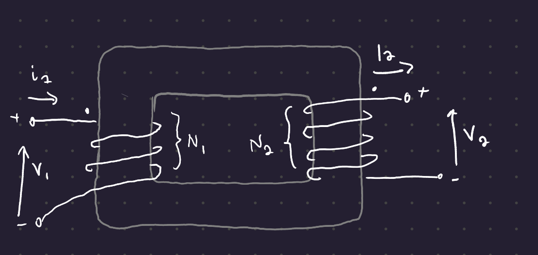
In a physical transformer, the core is a laminated stack to prevent eddy losses. The low voltage is wrapped close to the core, and the high voltage coil is wrapped directly on top of the low voltage coil.
DC is making a comeback - nonrthwest of China has big wind farms, so they have a HVDC transmission line (which requires only + and -, rather than 3 cables, making it cheaper over long distances).
Definition 1 (Transformer) A passive electrical device that changes the voltage of an AC supply through the action of a magnetic field.
1 Ideal Transformers
Transformers operate on Faraday’s Law:
E = -N\frac{d\phi}{dt}
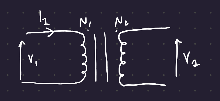
Transformers have a primary and a secondary coil with AC current flowing through them. This creates a changing magnetic field. As you increase the current through the primary, the flux begins to link the primary and secondary coils, resulting in an induced voltage in the secondary coil.
The voltage in the secondary is a function of the flux, which is a function of the number of turns in the primary and the secondary. More turns in the primary = more flux generated; more turns in the secondary = more voltage generated.


V_1 = N_1 \frac{d\phi}{dt}
The secondary senses the same alternating magnetic field in the absence of any leakage, so
V_2 = N_2 \frac{d\phi}{dt}
Thus the voltage produced is a function of the ratio of turns in the primary and the secondary:
V_2 = \frac{N_2}{N_1}\ V_1
The ratio N_2 / N_1 = n is the turns ratio of the transformer.
Since the power entering an ideal transformer is equal to the power exiting,
V_1 \ I_1 = V_2 \ I_2
The phase angle of the primary and secondary voltages in an ideal transformer are the same, as are the phase angles of the primary and secondary currents. Thus, the power in the transformer is the same on each side:
\begin{align} P_{in} &= V_1\ I_1 \ \cos \phi_1 \\ P_{out} &= V_2 \ I_2 \ \cos \phi_2 \end{align}
The primary and secondary windings of an ideal transformer have the same phase angle \phi and therefore the same power factor.
The phase equivalent circuit for a transformer looks a lot like the equivalent circuit for the induction motor, without the airgap.
You use the turns ratio to simplify the circuit:
V_2' = V_2/n
V_2' is the current across the load Z.
I_2' = nI_2
Same as the induction machines, you can determine the properties of a transformer by performing a no-load test.
2 Three-phase transformers
As usual, you can connect a 3 phase transformer in star or delta configuration.